I’m a big fan of LED lighting; especially interactive LED lighting so over the past two or so months I was working on a little side project that uses an Arduino Uno to read two IR receivers for beam breaks at the top and bottom of my stairs and shows an LED pattern while the person is walking up or down the stairs. All the code is open source on GitHub under the LGPL.
First, here’s the finished product in action:
The concept is pretty simple, the Arduino powers two IR transmitters at 38kHz. One at the bottom of the stairs and another at the top. Immediately across from the transmitters are two IR receivers. Again, one at the top and one at the bottom. When the receiver detects a beam break by someone walking between the transmitter and receiver, the receiver sends a signal to the Arduino which calls a function to make the LEDs display a pretty color.
The parts I used:
- Arduino Uno R3 (http://www.adafruit.com/products/50)
- Adafruit 36mm 12V LEDs (http://www.adafruit.com/products/683)
- 12V 5A power supply for the LEDs (https://www.adafruit.com/products/352)
- 2.1mm barallel plug adapter (https://www.adafruit.com/products/368)
- Two IR transmitters (https://www.sparkfun.com/products/10732)
- Two IR receivers (https://www.sparkfun.com/products/10266)
- About 150ft of 22 AWG hook-up wire (https://www.adafruit.com/products/290)
The wiring diagram:
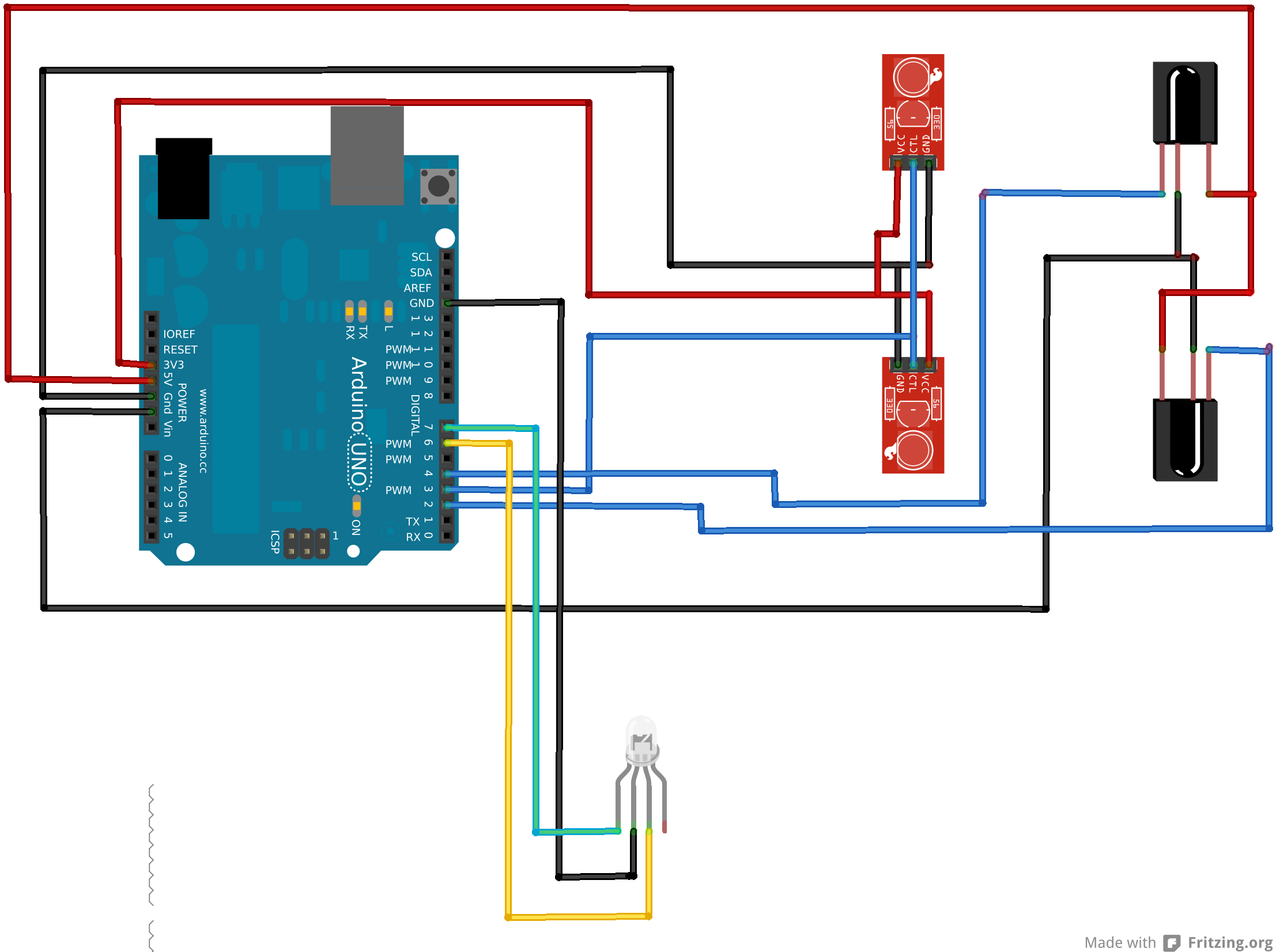
I couldn’t find a symbol for an LED strand so that’s what the LED at the bottom represents. There should be the two wires from the external power adapter running to the LED strand as well, but they aren’t shown in this diagram. Obviously, the IR transmitters and receivers should be farther apart from one another, but you get the overall idea. I highly recommend building all of this on a breadboard. I spent entirely too much time trying to figure out why things weren’t working (receivers not triggering, LEDs flickering, etc.) because I soldered everything together poorly.
The hardware is only half the story. The code is even more confusing that the circuit above. First, in order to make the IR transmitter modulate at 38kHz, the Arduino’s timers must be utilized. Thankfully, Ken Shirriff has an excellent IR library for Arduino. With some help from his blog, I was able to create a single function that enabled the IR transmitters to modulate at 38kHz.
1
2
3
#define TIMER_PWM_PIN        3
#define TIMER_ENABLE_PWM     (TCCR2A |= _BV(COM2B1))
#define TIMER_DISABLE_INTR   (TIMSK2 = 0)
1
2
3
4
5
6
7
8
9
10
11
12
13
14
15
16
17
18
19
20
void enableIrTransmitters(int khz) {
   // Disable the timer 2 Interrupt (which is used for receiving IR)
   TIMER_DISABLE_INTR;

   pinMode(TIMER_PWM_PIN, OUTPUT);

   // When not sending PWM, we want it low
   digitalWrite(TIMER_PWM_PIN, LOW);

   // The modulation frequency is F_CPU / 2 / OCR2A (output compare register 2A)
   const uint8_t pwm_val = F_CPU / 2000 / IR_KHZ;

   TCCR2A = _BV(WGM20);
   TCCR2B = _BV(WGM22) | _BV(CS20);
   OCR2A  = pwm_val;
   OCR2B  = pwm_val / 3;

   // Enable PWM output on pin 3
   TIMER_ENABLE_PWM;
}
Lastly, the setup() function which sets the pin mode for the receivers, calls the enableIrTransmitters() function, and unrelated to the IR, seeds the random number generator, and starts the LED object.
1
2
3
4
5
6
7
8
9
10
11
12
13
void setup() {
   pinMode(IR_DETECT_UPSTAIRS_PIN, INPUT);
   pinMode(IR_DETECT_DOWNSTAIRS_PIN, INPUT);

   enableIrTransmitters(IR_KHZ);

   lights.begin();

   randomSeed(analogRead(0));

   // Wait a second to prevent "phantom" signals from the IR receivers on start up
   delay(1000);
}
To control the LEDs, Adafruit has a wonderful Arduino library for controlling WS2801 LEDs. This allows my code to only worry about generating the proper RGB values and letting the library handle sending them to the LEDs. A simple example of using the library is the function below which fades from one color to another. The lights object is an instance of the Adafruit_WS2801 class.
1
2
3
4
5
6
7
8
9
10
11
12
13
14
15
16
17
18
19
20
21
22
23
24
25
void fade_color(unsigned char old_red, unsigned char new_red, unsigned char old_green, unsigned char new_green,
unsigned char old_blue, unsigned char new_blue, int steps, int delay_time) {
float red_step = (float)(new_red - old_red) / steps;
float green_step = (float)(new_green - old_green) / steps;
float blue_step = (float)(new_blue - old_blue) / steps;
float cur_red = old_red;
float cur_green = old_green;
float cur_blue = old_blue;
for(int i=0; i<steps; i++) {
cur_red += red_step;
cur_green += green_step;
cur_blue += blue_step;
for(int j=0; j<lights.numPixels(); j++) {
lights.setPixelColor(j, (unsigned char)cur_red, (unsigned char)cur_green, (unsigned char)cur_blue);
}
lights.show();
delay(delay_time);
}
}
There are a few more light patterns in the code and a random one is selected each time a beam break is detected, but they get lengthy and complicated so I won’t go into them here. The loop() is what triggers these by simply checking for a signal from the IR receivers.
1
2
3
4
5
6
7
void loop() {
   if(!digitalRead(IR_DETECT_UPSTAIRS_PIN)) {
      show_stair_lights(DOWN);
   } else if(!digitalRead(IR_DETECT_DOWNSTAIRS_PIN)) {
      show_stair_lights(UP);
   }
}
By checking which receiver was tripped, we can tailor the lighting effect to a person walking up or walking down the stairs.
Some possible future expansions to this project are adding another strand of LEDs to the other side of the stairs. As you can see in the video above, the effect would be greatly enhanced by having another strand of LEDs. Given that the power supply for the LEDs has enough power to run two strands, it would be a relatively minor modification. I’m sure I’ll also continue to add new light effects as I think of them. Overall, I’m happy with the result, but given the amount of time and money it took, I’ll probably be sticking to pure software projects for the foreseeable future.